Masonry Wall - Modeling
The masonry wall panel element allows you to easily model, analyze and design masonry walls for in plane
Masonry Wall Input
The Wall Panel Editor gives some specific information and options for modeling/analysis of masonry walls.

Click on image to enlarge it
Masonry View Controls
Masonry Wall Panels have the following view controls:
View Controls
|
Icon |
Control |
Description |
|---|---|---|
|
|
Regions |
The Regions icon lets you turn the display of regions on or off. |
|
|
Lintel |
The Lintel icon lets you turn the display of lintels on or off. |
|
|
Out-Plane |
The Out-Plane icon lets you turn the display of out of plane reinforcement on or off. |
|
|
In-Plane |
The In-Plane icon lets you turn the display of in-plane reinforcement on or off, after you have solved the model. |
Openings / Lintels
![]()
Click on image to enlarge it
In the Wall Panel Editor, you have the option of adding rectangular openings to masonry wall panels. To draw an opening, select the Openings icon and then select two nodes or grid intersections which make up the two diagonal corners of your opening. When an opening is drawn a lintel is automatically created above the opening. To view or edit the properties of a masonry lintel, double-click inside the boundary of the drawn opening. This brings up the Editing Properties window for that particular lintel.

Click on image to enlarge it
This window shows the design options set in the Wall Design Rules - Lintel spreadsheet to design/analyze your lintel. If you have multiple lintels in a wall and want a specific design that differs from the other lintels, you can
The following table includes the different input options available for designing/analyzing lintels.
Lintels Input Options
|
Control |
Description |
|---|---|
|
Depth |
Depth is the depth of the lintel. |
|
Bearing Distance |
Bearing Distance is the bearing length at either end of the lintel. This is used to calculate the effective length of the lintel. |
|
Bar Size |
Bar Size option is the reinforcement size you wish to use for the main reinforcing in the lintel. |
|
Bars Per Layer |
Bar Per Layer is the number of bars you wish to have in a given layer of reinforcement. There is also an option to have this value optimized based on geometry of the section, and also the number of layers that you have defined. |
|
Number of Rebar Layers |
Number of Rebar Layers lets you have multiple layers of reinforcement in the lintel. |
|
c/c Spacing of Layers |
c/c Spacing of Layers is the distance between layers (if there is more than one). |
|
CL Rebar to Lintel Bot |
|
|
Stirrup Size |
Stirrup Size is the size of stirrup to be added to the lintel if required. |
Regions
Within the Wall Panel Editor, you have the option of creating rectangular regions within the masonry wall panel. Regions are used to define reinforcement in different parts of the wall. Each region will be assigned a uniform reinforcement, which may be different than the reinforcement in other parts of the same wall.
If no regions have been drawn on a wall, then they are automatically generated when a solution is performed.
To automatically generate regions prior to running a solution, click the Automatic Wall Regions
![]()
To manually draw regions, select the Manual Wall Regions button and use your cursor to select two nodes or grid intersections which make up the diagonal corners of the region. To exit this tool right-click your mouse. 
To view or edit the properties of a masonry region, double-click inside the boundary of the drawn region. This brings up the

Click on image to enlarge it

Click on image to enlarge it
For masonry wall panel regions, you can also customize regions which makes it different than the Wall Design Rule. To use a custom design region, select Convert to Custom Design Region. When using the custom option, the program uses all of the information set in the Region Editor and disregards any information given by the design rule for that region.

Click on image to enlarge it
Within this dialog you can specify the properties which will be used for the design of the region. The program can optimize the bar spacing and the boundary zone width based on code checks. The block size, reinforcing strength and the method of self-weight calculation are defined in the Design Rules under the Masonry Wall tab.
Here we will walk through the different input options available for designing/analyzing regions:
Transfer - This option lets you choose whether or not you want this region to transfer
- These transfer options are only available when you have defined a region above or below an opening.
- If you do not choose to check these transfer options you will see design results for regions above and below openings.
Axial - Lets you to define properties of a region based on axial forces.
- Block Grouting - Lets you to define how you want your wall grouted. If you choose "Partially Grouted" the program will optimize the grout spacing with the Bar/Grout Spacing
- Reinforced - Gives the option of designing the wall as reinforced or unreinforced.
- Bar/Grout Spacing - This Lets you to define the bar/grout spacing. If you have the "Optimize" box checked, the program will optimize the reinforcement spacing based on code checks.
-
-
Location - This defines how you want to lay out the reinforcement in your region. Each Face puts reinforcement on both faces of a given cell. Staggered alternates the bars to either face of wall region.
Note: When using the staggered option, you are selecting to space the bars at each face at double the bar/grout spacing defined above. For example, if you have a staggered spacing at 24" oc you have a bar on the outside face at 48" oc and a bar on the inside face at 48" oc. These bars are staggered, thus you have grout filled cores at 24" oc.
In-Plane
- Vertical Bar Size - Lets you to define vertical bar size for the boundary zones.
- Bars Per Cell - Lets you to define one or two bars per cell.
- Boundary Zone Width - You must define a boundary zone width, but RISA optimizes the width if the "Optimize" box is checked. Note: If you have the optimize checkbox selected, the program optimizes the boundary zone width based on code checks.
- Horizontal Bar Size - Lets you define horizontal bar size to be used if horizontal reinforcing is required.
- 1.5x Shear Increase - This option may be required in high seismic zones. The option is available per section 7.3.2.6.1.2.
Merge Lintels
When an opening is drawn in a masonry wall panel, you will notice that a lintel beam region is automatically created above the opening. If you have multiple openings, you may want to merge the individual lintels into one. To do this, click the Merge Lintels icon.
![]()
If you have two lintels you want to merge, then click within each of the openings to merge them into one. If you have multiple lintels that you want to merge, click inside of the two openings that define the ends of the merged lintel that you want. You will see that this merges your multiple openings into one. To exit out of this tool right-click your mouse.
When merging lintels, the top edges of the lintels have to be identical. If, once you have merged lintels, you delete one of the openings the entire lintel will be deleted. At that point, you have to delete any openings left in the wall that don't have a lintel over them.
Optimization / Limitations
Optimization
The program optimizes masonry walls and lintels based on the required demand forces. The program can optimize:
- Vertical bar/grout spacing for
- Boundary zone widths for in plane flexural design.
- Horizontal bar spacing for in plane shear design.
- Reinforcement bars for lintel flexural design.

Click on image to enlarge it
To update the stiffness portion of the wall, the program must re-solve your model with these updated stiffnesses as this will change the distribution of forces through the model. By
By
After the solution is run (with or without optimization) the design results are based on the stiffness used in the last iteration (
The program will always present results in the output that coincide with the stiffness used in the final solution.
Suggested Design
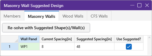
In the Suggested Design spreadsheet you will get a list of wall panels in your model that are not yet fully optimized, showing the vertical bar and/or grout spacing of the last iteration (Current Spacing) and the program optimized spacing (Suggested Spacing). From here you have the ability to Use Suggested? which means that you want to re-run the solution with the Suggested Spacing. You can choose this for each wall panel individually. Once you have these checkboxes checked appropriately, click the

After this, the stiffness matrix is re-formulated and may cause some redistribution of loads through the model. Because of this, the Suggested Spacing may also update and you may need to Use Suggested? multiple times to converge on a solution.
- If the wall does not show up in the Suggested Design spreadsheet, then the current wall panel settings used are the optimal ones.
- For more information on wood wall optimization see the Wood Wall - Design topic.
- For more information on member optimization see the Design Optimization topic.
- Concrete walls do not show up here because the reinforcement optimization does not affect the stiffness of the wall.
Lintels
For masonry lintels you must input the dimensions, bar size and number of layers of bars for the lintel, but are given the option of optimizing how many bars are in a given layer. If you provide a max/min number of bars in the Wall Design Rules - Masonry Lintel tab then the program will optimize the number of bars in a layer.
Lintel Reinforcement Placement Check
The program will do a check to see that the reinforcement in the lintel will fit properly. The available width for reinforcing in the lintel is based on the width of block, thickness of grout between the block and the reinforcement, and it assumes there will be a double-leg stirrup.

where
tgrout = 0.5 in (per Section 6.1.3.5 of ACI 530-13; the program assumes coarse grout)
dbstirrup = diameter of stirrup (from the Wall Design Rules - Masonry Lintel tab)
Note that we use a minimum bar spacing equal to the minimum of either db or 1".
Regions
For masonry regions, there
Limitations
- Openings and regions must be input only in RISAFloor if you are using RISA-3D and RISAFloor in tandem.
- For sloped walls due to sloping floors, openings and regions can not be defined in the upper triangular area of the wall panel. These openings are not supported at this time. This will be addressed in a future version.
- For areas of masonry wall panels that are not defined as a region, the stiffness of the wall is assumed to be that of an ungrouted masonry wall and the weight of the wall is assumed to be that of a fully grouted wall.
- Masonry has specific requirements regarding the spreading out of concentrated loads at certain angles and for certain depths (Section 5.1.3). These provisions are not considered in RISA, as the finite element mesh stiffness is what determines load path. See the Wall Panels - Load Attribution topic for more information.